This post covers NetApp MetroCluster, a business continuity solution which provides synchronous data replication between two sites within 300km. Before getting into the MetroCluster details, let’s have a quick review of the NetApp High Availability feature first.
When a Controller Fails
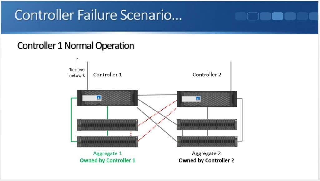
The controller is the brains of the storage system and provides clients access to their data. If a controller went down then clients would lose access to data if redundancy was not in place. Controllers are arranged in pairs to provide this redundancy. Each controller in the pair controls its own data, and can additionally take over for its peer if that peer goes down. Multiple HA pairs can be deployed in the same cluster to provide additional capacity and performance.
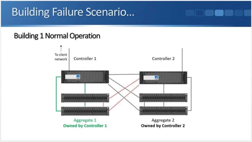
Based on the diagram above, we have a standard high availability pair with “Controller 1” and “Controller 2”. The disk shelves are shown under the controllers. In NetApp ONTAP, disks are always owned by one and only one controller and are grouped into aggregates. Per the diagram above, Aggregate 1 is owned by Controller 1 while Aggregate 2 is owned by Controller 2.
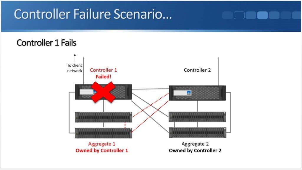
Controller 1 and Controller 2 act as High Availability partners for each other. If Controller 1 fails, Controller 2 will detect it.

A controller can detect its peer has failed through the physical High Availability connection, or through hardware assisted failover with the help of Service Processors.
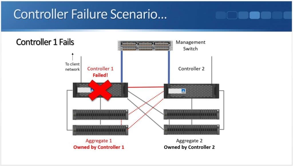
Controller 2 will take temporary ownership of the disks when Controller 1 fails.
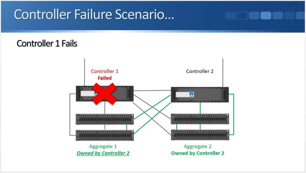
Controller 2 now owns Aggregate 1 and Aggregate 2 and clients can still reach all of their data.
When a Whole Building Fails
High Availability helps when we have a controller failure, but what if it’s not just a controller but the whole building which goes down?
The above example shows Controller 1 and its disk shelves in one building while Controller 2 and its disk shelves are in a different building.
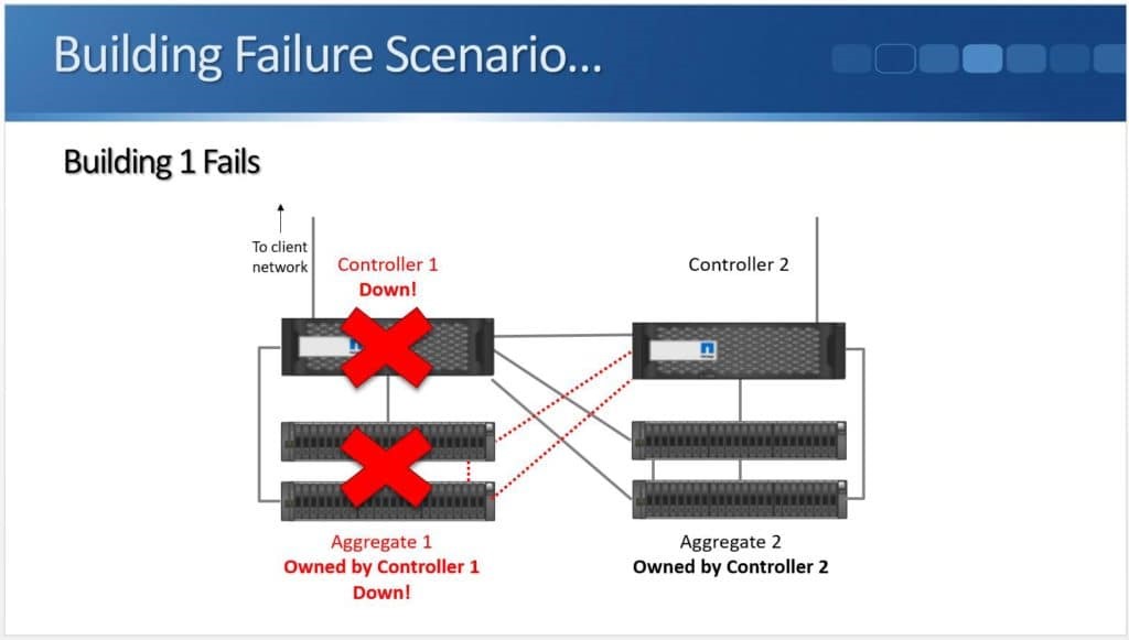
We have a power outage that causes us to lose the controller and the disk shelves. Through the High Availability connection, Controller 2 will detect the failure as it’s no longer receiving a keepalive signal.
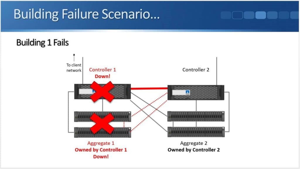
However, Controller 2 won’t be able to take control of Aggregate 1 because the disk shelves are down. Aggregate 1 is no longer available due to the power failure.
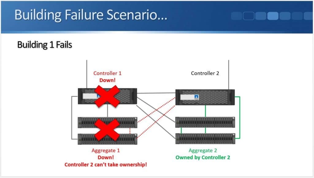
So High Availability gives us redundancy for our controllers, but it doesn’t give us redundancy in case we lose the entire building. This is where NetApp MetroCluster comes in.
MetroCluster
In the event of a building failure, NetApp MetroCluster gives us redundancy by combining High Availability and SyncMirror. SyncMirror is used to mirror the aggregates to a disk shelf in each building. We can selectively choose which aggregates to mirror. We can choose to mirror all of them or we can cut down on disk hardware costs by only mirroring our mission critical aggregates.
When a Building Fails – with MetroCluster
Let’s see how NetApp MetroCluster works.
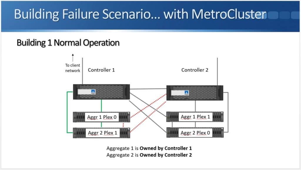
We have Controller 1 in one building and Controller 2 in another. Both have their own disk shelves. Aggregate 1 is still owned by Controller 1, but it is SyncMirrored across the two buildings. Plex 0 is in one building and Plex 1 is in the other building. Whenever data is written to the aggregate it is written to both plexes at the same time, so both buildings end up with the same copy of the data. The same applies to Aggregate 2 as well.
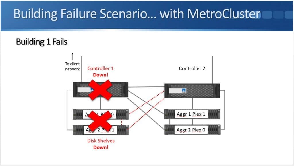
Building 1 fails so we lose controller 1 and its disk shelves, but because Aggregate 1 and Aggregate 2 are still available in the other building, clients won’t lose access to their data.
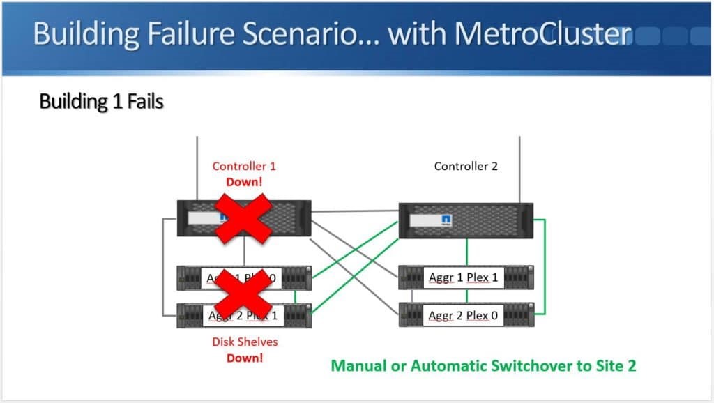
Switchover to the other building can either be done manually or automatically. This will be discussed in more detail later.
Recovery Point Objective (RPO)
SyncMirror and MetroCluster use synchronous replication. Data is written to both buildings before the acknowledgment is sent back to the client. NetApp MetroCluster has a Recovery Point Objective of zero due to synchronous replication. No data is lost in the case of an outage.
MetroCluster in 8.3.0
MetroCluster has gone through a few different implementations in NetApp ONTAP. It first became available in ONTAP version 8.3.0. MetroCluster had been available in 7-mode for a long time, and was practically the last major feature to be ported over to Clustered Data ONTAP.
NetApp MetroCluster only supported a four node setup in ONTAP 8.3.0. This is also still available in later versions of ONTAP. With the four node MetroCluster setup, both sites host an independent two node cluster. We can’t have three or more as MetroCluster only runs across two sites.
The two nodes in each site are a High Availability pair for each other. SyncMirror mirrors the aggregates across both sites – not across both nodes in the same site but across both actual sites. It’s an active-active configuration where each site serves read requests to local clients from the local Plex.
The remaining controller in the same site will take over its aggregates if a single controller fails as shown in the standard High Availability scenario. If both controllers in a site go down, meaning the entire site is down, you can failover to the other site. The sites can be up to 200 kilometres apart.
The Distance From Controller to Shelf
SAS only supports short cable lengths so if SAS is being used for the controller to disk shelf connections, there will be a controller to shelf distance problem. So how can we cable controllers to a disk shelf in another building?
Fabric-Attached MetroCluster
Fibre Channel supports long length cables. A pair of Fibre Channel switches can be installed in both sites. The next problem that we have is the current models of disk shelves have SAS, not Fibre Channel ports. How are we going to actually get the cable into the disk shelf, if we’re using these long distance Fibre Channel cables to go from the controller to the shelves in the other site?
ATTO FibreBridge
This is where the ATTO Fibre Bridge comes in, a Fibre Channel to SAS Gateway. It has both a Fibre Channel and a SAS port, and it can convert between the two. The controller connects to the Fibre Bridge with Fibre Channel cables via the Fibre Channel switches while the Fibre Bridge connects to the disk shelves with SAS cables.
Cabling in Fabric-Attached MetroCluster
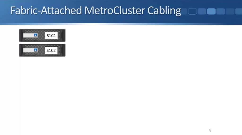
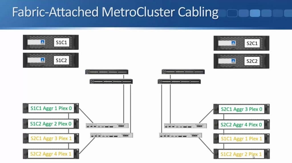
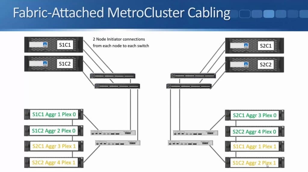
Let’s take a look at the NetApp MetroCluster Cabling for Fabric-Attached MetroCluster. It is called Fabric-Attached MetroCluster since it uses Fibre Channel switches.
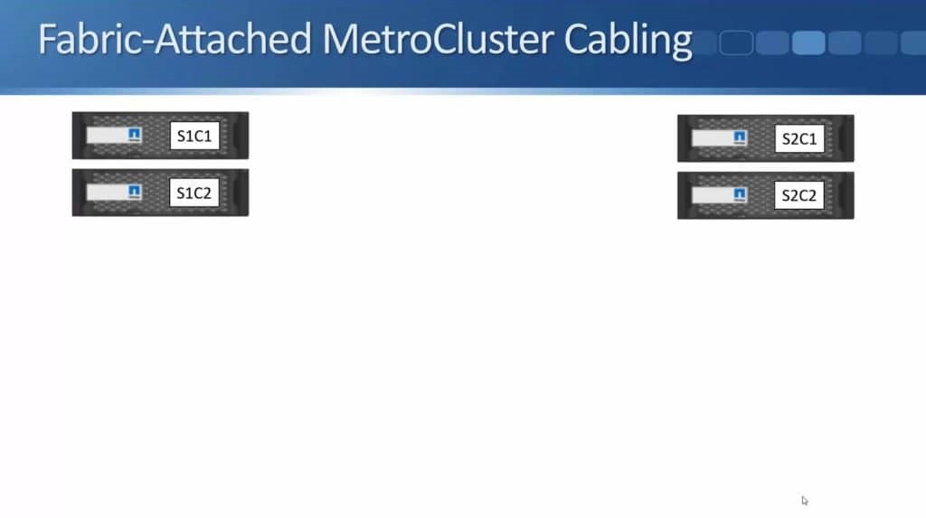
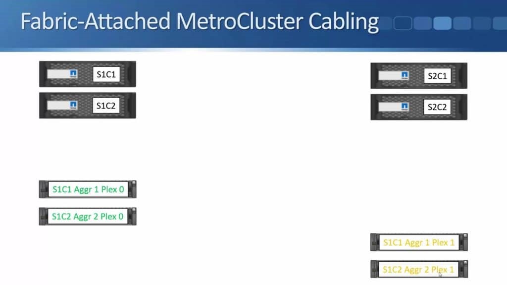
In the below example, we have an HA pair for four node MetroCluster in Building 1, Site 1 Controller 1 (S1C1) and Site 1 Controller 2 (S1C2).
We also have an HA pair in Building 2, Site 2 Controller 1 (S2C1) and Site 2 Controller 2 (S2C2).
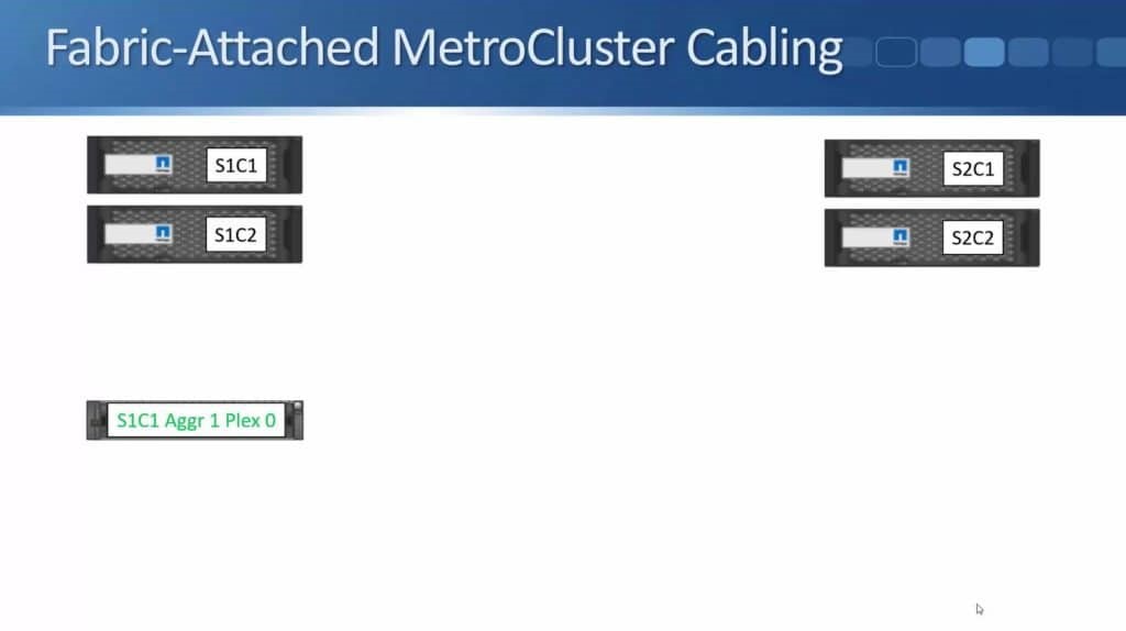
Next, let’s take a look at the disk shelves. In Building 1 we have Aggregate 1 Plex 0 owned by Site 1 Controller 1.
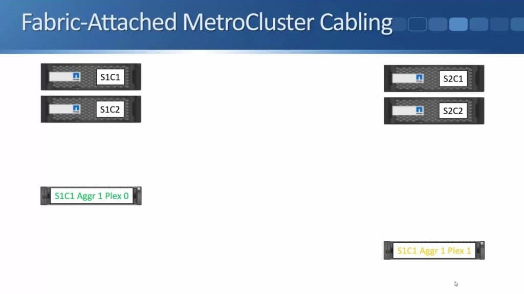
Then we have a SyncMirror Plex (Plex 1) for Aggregate 1 located at the other site, owned by Site 1 Controller 1.
Then we have a second aggregate, Aggregate 2 Plex 0, owned by Site 1 Controller 2.
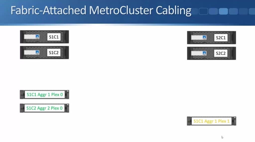
Also SyncMirror Plex (Plex 1) for that aggregate in Site 2.
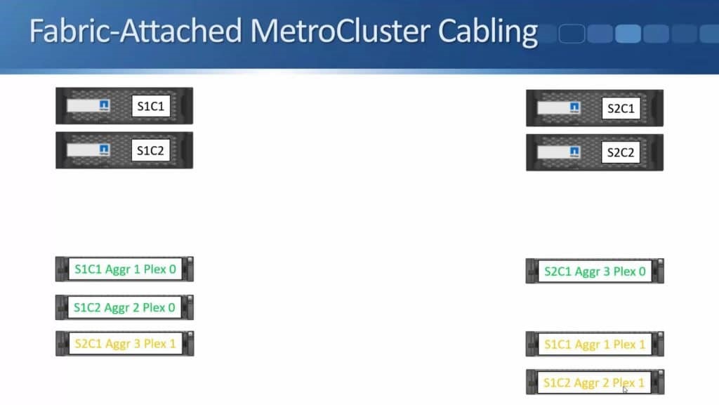
Next is the third aggregate, Aggregate 3 Plex 0 in site 2 owned by Site 2 Controller 1.
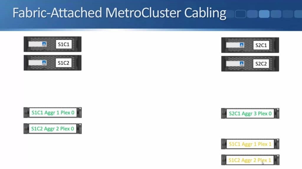
We also have a Plex 1 for that in Site 1. Both Plexes are owned by Site 2 Controller 1.
Lastly, we have Aggregate 4 owned by Site 2 Controller 2.
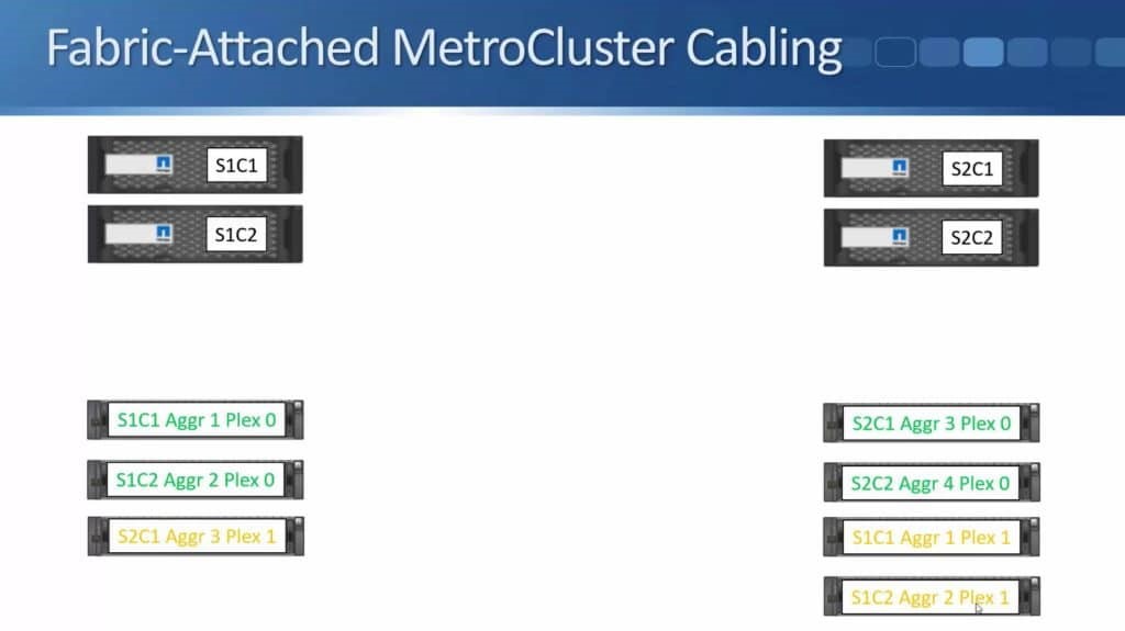
Building 2 has Plex 0 while Plex 1 is in Building 1.
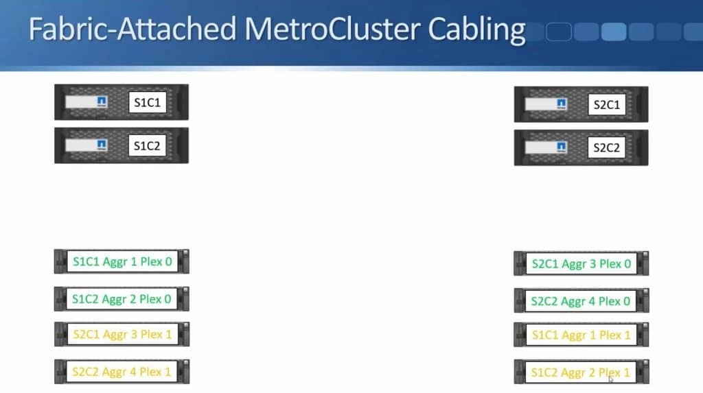
In the example shown, we use four aggregates and both sites have single stack of disk shelves to make the diagram clear and easy to understand. You can have as many aggregates as you want and you can also have multiple stacks in the different sites if needed.
Now let’s take a look at ATTO Fibre Bridges.
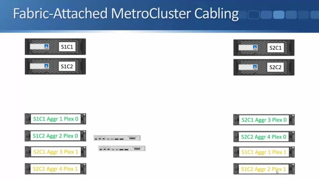
We cable these up to the disk shelves using SAS cables. In Site 1, Fibre Bridge 1 will be connected to the top shelf in the stack.
Then going down, it will be daisy chained from there.
Then the Fibre Bridge 2 will be connected to the bottom shelf in the stack.
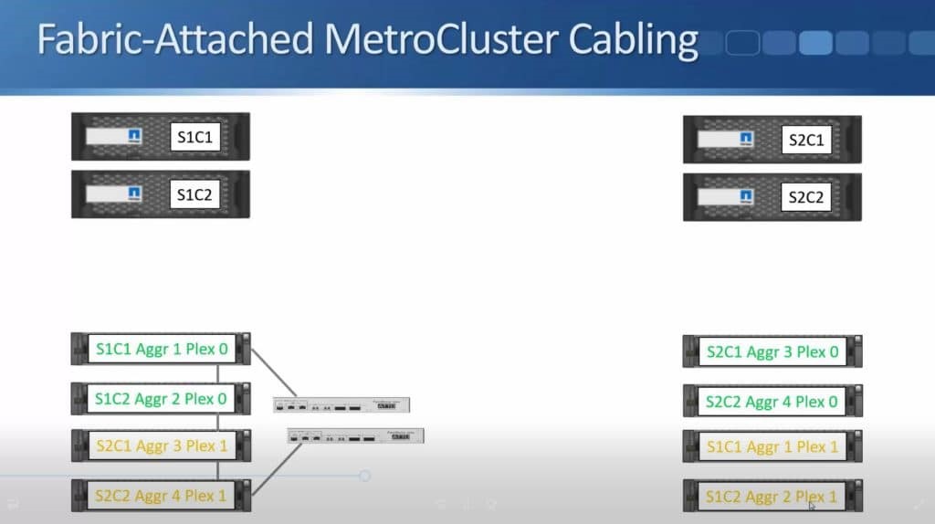
And once we are done with Site 1, we will do the same on Site 2.
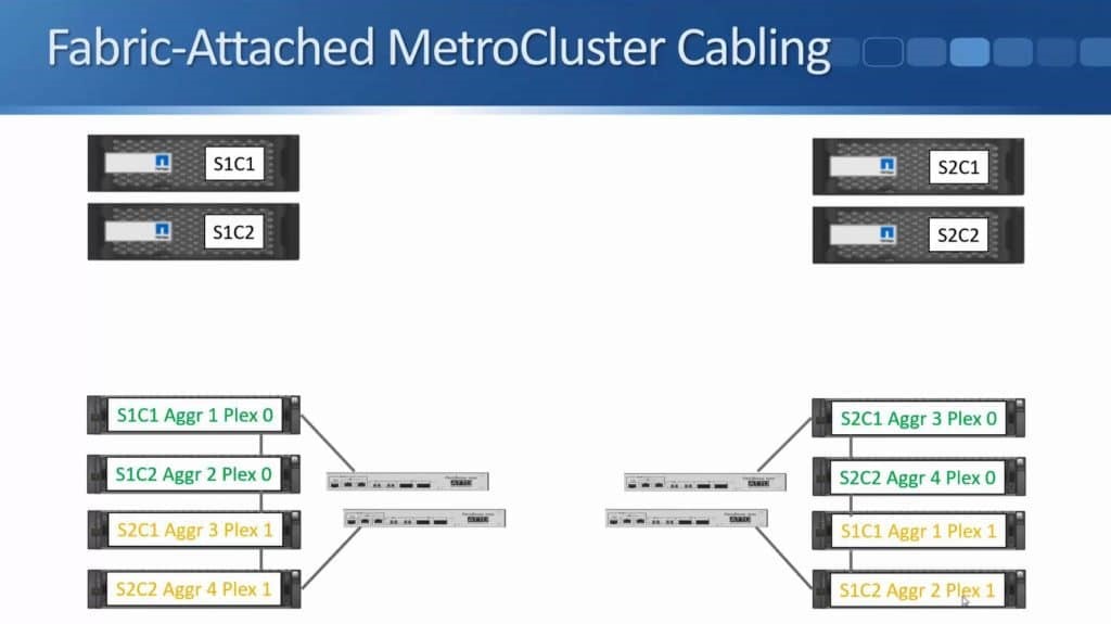
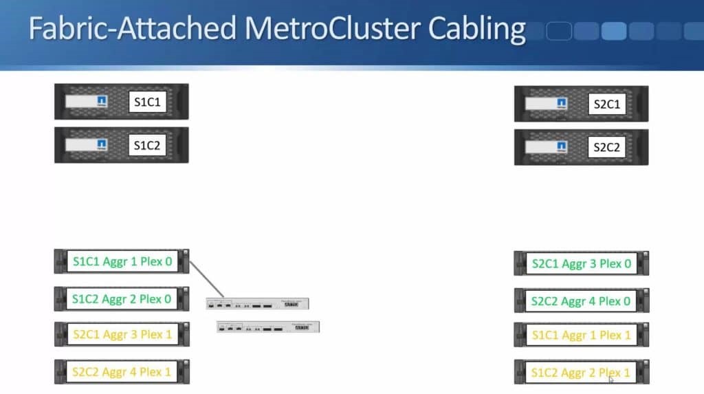
The next thing that we need is the Fibre Channel switches.
The switches are from either Cisco or from Brocade. Fibre Channel Switch 2 will be connected to Fibre Bridge 2 while Fibre Channel Switch 1 will be connected to Fibre Bridge 1. Both will be using Fibre Channel cables.
The Fibre Channel switches in Site 1 are shown above. The same setup will be implemented in Site 2.
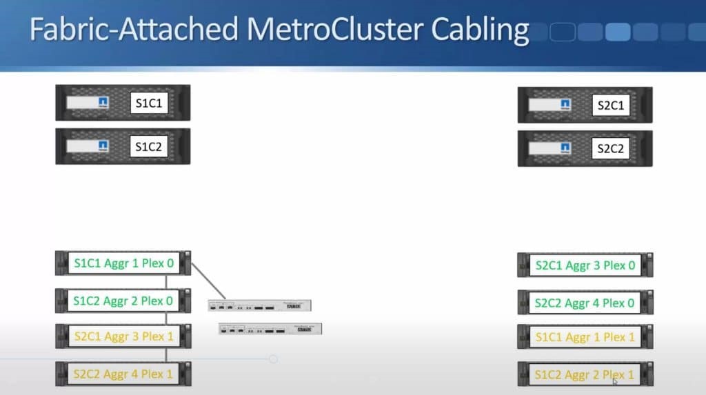
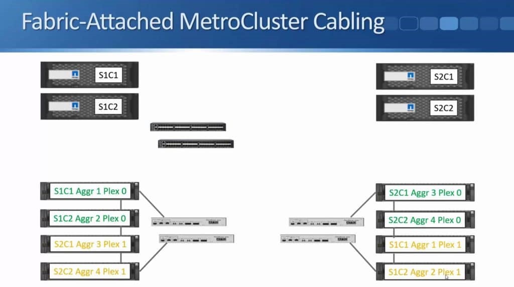
We connect the controller to the Fibre Channel switches using Fibre Channel cables. Site 1 Controller 1 will be connected to the first Fibre Channel switch and to the second Fibre Channel switch as well.
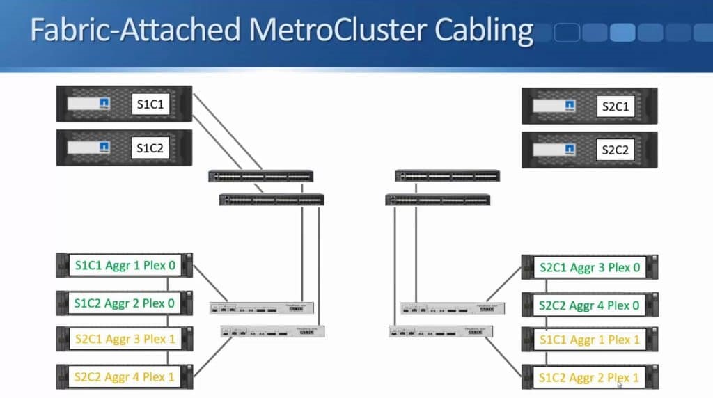
We do the same for Site 1 Controller 2, it is also connected to both switches.
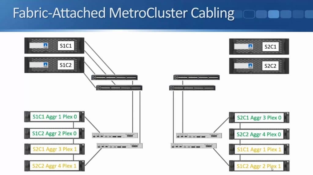
The above diagram only shows one connection to make it tidier but there’s actually two connections from each node to each switch.
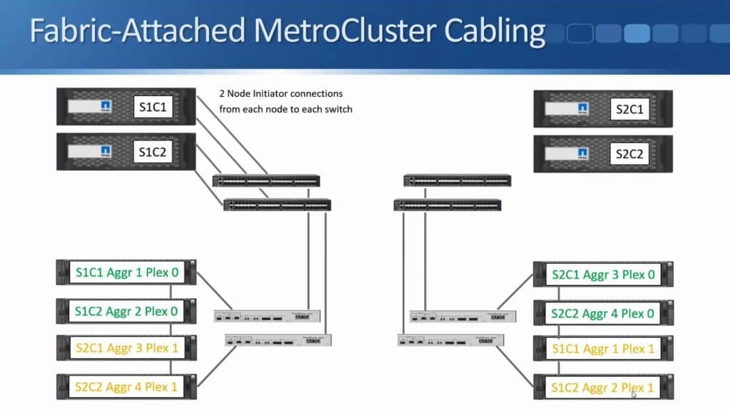
The above diagram shows the Node Initiator connections, which give the controllers connectivity over Fibre Channel to the disk shelves on both sides.
Site 2 is also configured with similar connections.
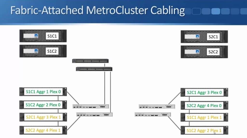
The controllers have connections to the disk shelves in the same site but because we are using SyncMirror to write to both locations they need to have connections to the disk shelves in both sites. That’s the reason we connect both Fibre Channel switches together. Fibre Channel Switch 1 in both sites are connected to each other, and Fibre Channel Switch 2 in both sites are connected to each other.
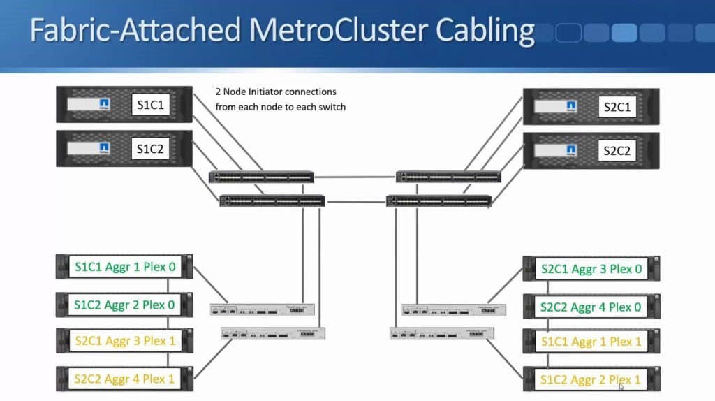
The above diagram only shows one connection, but you can actually have up to four connections between each pair of switches bundled into a port channel. As you can see, there’s no single points of failure. There are two controllers in each site, which are configured as an HA pair for each other. We have two Fibre Channel switches in each site, two Fibre Bridges in both sites, and the aggregates are SyncMirrored across both sites as well.
FC Virtual Interfaces
In the previous diagram, cabling showed the Node Initiator connections from the controllers to the disk shelves in both sites for reading and writing to disk during Consistency Points. Writes still work in the same way as usual though, where they are written to NVRAM before being written to disk. NVRAM mirroring also takes place over the Fibre Channel network between both sites. It uses Separate 16-Gbps Fibre Channel Virtual Interface (FCVI) connections from the controllers.

We now have a Fibre Channel Virtual Interface (FCVI) connection from each controller going to both Fibre Channel switches in the same site. Those are the connections for Site 1 Controller 1.
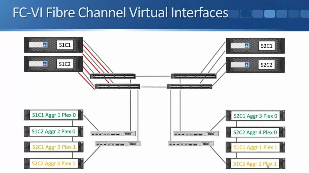
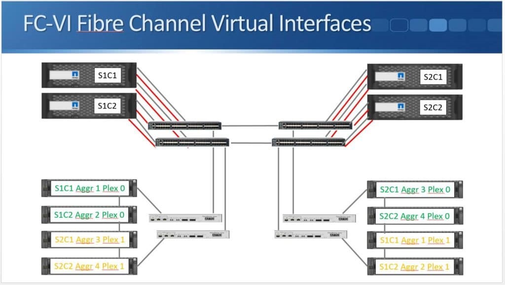
Then we do the same for Site 1 Controller 2 as well as for the two controllers in Site 2.
For the Node Initiator connections, we’ve got two Node Initiator connections from each node to each switch. These are for our reads from disk and for our writes during Consistency Points. For the FCVI connections which are being used for the initial NVRAM mirroring between the two sites, we’ve got a single connection from each controller going to both switches in the same site. The FCVI connection has to use a dedicated 16 G connection while the Node Initiator connections can use a standard Fibre channel port on the controller.
Configuration Replication
SVM, LIF, volume, and LUN configuration information are replicated between the two sites using the Configuration Replication Service (CRS). Just like SnapMirror traffic, it replicates over a standard IP network, using cluster peering and inter-cluster Logical Interfaces (LIFs).
There are three different types of connections on our controllers:
- Node Initiators – for connectivity to our disks going over Fibre Channel
- FCVI – for NVRAM mirroring that also goes over the same Fibre Channel network.
- CRS connectivity – uses Inter-cluster LIFs going over an IP network.
Connecting From Clients
Cluster identity is preserved during a switchover from one site to another. Clients connect to the same IP addresses or WWPN’s they were using before at the original site when it failed. The client data network must therefore span both sites. The same layer 3 subnet has to be available on both sites since the clients connect to the same IP address. You can use dark Fibre, an MPLS layer 2 VPN service, or a proprietary solution such as Cisco OTV (Overlay Transport Virtualization) for client protocols running over IP, like NAS or iSCSI, or a SAN fabric that spans both sites for Fibre Channel.
MetroCluster in 8.3.1
As previously mentioned, NetApp MetroCluster for Clustered Data ONTAP was released in version 8.3.0 which originally supported four node clusters. Support for two node MetroCluster was added when ONTAP 8.3.1 was released. Both sites host an independent single node cluster and the sites can switch over in case of a failure. There are three different supported two node configurations:
- Stretch MetroCluster
- Stretch MetroCluster with SAS Bridges
- Fabric MetroCluster
Stretch MetroCluster
The controllers are cabled directly to the disk shelves with NetApp proprietary long reach SAS cables in two node Stretch MetroCluster. We are not required to use Fibre Channel switches and ATTO Fibre Bridges like the ones we used in Fabric MetroCluster. The maximum distance is only up to 500 metres, it is not as long as Fibre Channel since we are using SAS cables.
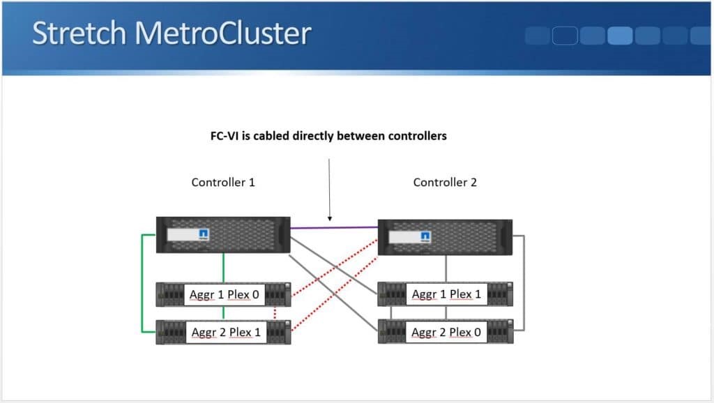
As you can see from the above diagram, setup is very similar to a standard High Availability.
Using SAS cables, the controllers are connected to the disk shelves. The Fibre Channel VI connection where is cabled directly between Fibre Channel ports on the controllers.
Stretch MetroCluster with SAS Bridges
The next type available is Stretch MetroCluster with SAS Bridges, where the controllers are not cabled directly to the dish shelves but via ATTO Fibre Bridges. It uses Fibre Channel but Fibre Channel switches are not being used here. The maximum distance is 500 metres.
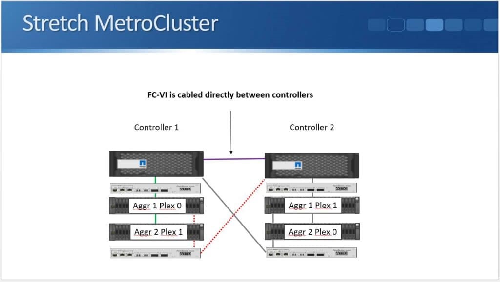
The above diagram shows the controllers have a single Fibre Channel connection to the ATTO Fibre Bridge in both sites and the ATTO Fibre Bridge then has a SAS connection going to the disk shelves. Then SAS connections are daisy-chained down through the stack. Again, we have the FCVI connection for the NVRAM mirroring between the two controllers.
Two Node Fabric MetroCluster
The last type is two node Fabric MetroCluster. The system is cabled the same way as the four node Fabric MetroCluster which was supported on 8.3.0. But the maximum distance is increased from 200km to 300km.
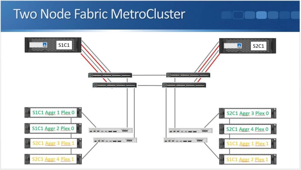
The above diagram shows that it is almost the same as four node Fabric MetroCluster except that we only have one node in each site.
MetroCluster in Version 9
When ONTAP 9 was released, we had another improvement in that ONTAP 9 supports eight node Fabric MetroCluster. With this, we have two HA pairs located in both sites where each HA pair is replicated to its secondary HA pair at the other site. The maximum distance is 200 km over Fibre Channel, or you can use the new option of Fibre Channel over IP (FCIP) which can go up to 300 km.
Switchover
Let’s see what we would do if we lost a site.
An automatic switchover will occur once a node undergoes a panic in a two node NetApp MetroCluster.
In order to prevent a split brain scenario, where both sites lose connectivity with each other and assume the primary role for all aggregates, switchover occurs manually or through the use of MetroCluster Tiebreaker software.
A split brain scenario has to be avoided at all cost because it can lead to different data being written to the Plexes for the same aggregate in both sites. Clients in Site 1 would be writing to Aggregate 1 in their site while clients in Site 2 would be writing to their Plex for Aggregate 1 in Site 2. As a result, we would have two different, inconsistent copies of the data in the same aggregate. We need to ensure this doesn’t happen.
Split Brain
The situation that could lead to a split brain is when both sites are up but lose connectivity to each other.
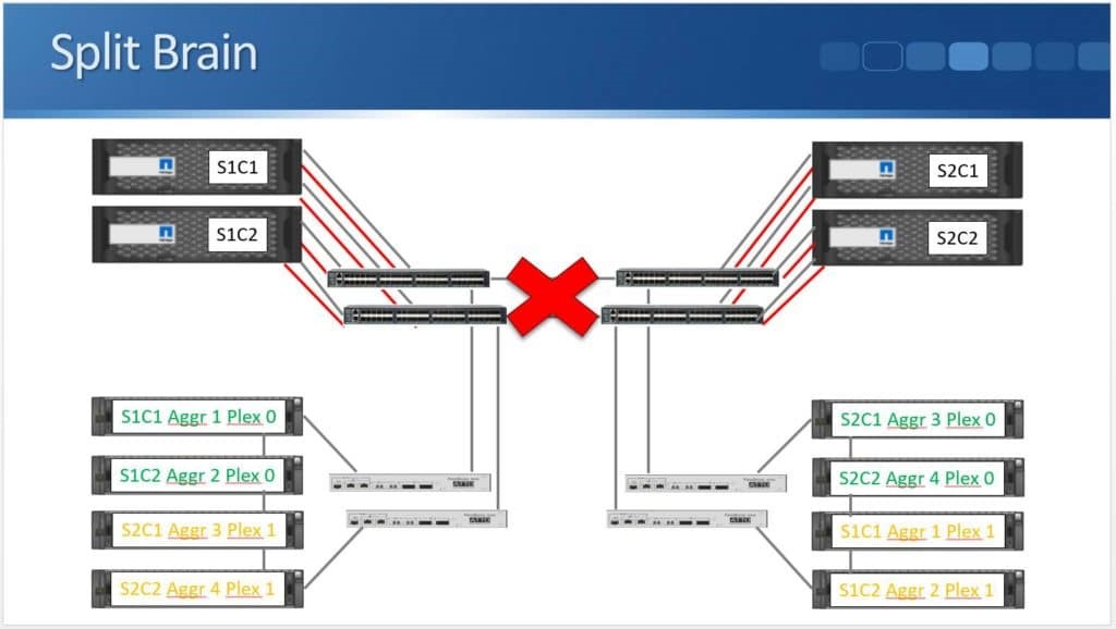
This is the reason why switchover doesn’t happen automatically by default. Normally, each site won’t know if the loss of connectivity was due to the site going down or just the network connection going down.
Manual Switchover
The first way to initiate a switchover is by doing it manually. The administrator verifies if a site really has gone down and if it needs to switchover to the other site. The command to use is “metrocluster switchover”. It will perform a graceful, negotiated switchover if we do this while both sites are still available. We can do this if we want to take a site down for maintenance.
The other command that we can use is “metrocluster switchover -forced-on-disaster true”. This is for us to force a switchover when a site has actually failed. The only issue that we have on manual switchover is that the whole process takes time, from learning that the site has failed, up to manually entering this command. We may want to speed things up.
MetroCluster Tiebreaker
Using MetroCluster Tiebreaker (MTCB), we can automate the switchover. MTCB is a Red Hat Java application that runs in a third site which has connectivity to both clusters. It independently monitors both sites, and if issues are detected, it will send SNMP alerts. In the event of a site failure, it can also be configured to automatically switchover. When using MCTB, the Recovery Time Objective (RTO) is 120 seconds for automatic switchover.
It works by establishing SSH Secure Shell sessions with each node’s node management IP address to verify that they’re up. If the SSH session to a node goes down, MCTB will first check the HA status within the site to verify if it’s just that one node that has gone down and that it’s failed over to the HA peer in the same site. It will be declared unreachable if both nodes of an HA pair is unresponsive.
To ensure that it is not just the network from the third (MCTB) site to the first MetroCluster site that’s gone down, MCTB will ask the second MetroCluster site via SSH if it has connectivity over the FCIV connection or the inter-cluster IP network to the first site. This verifies a site failure because connectivity has been lost through two separate paths. At this point you can configure MCTB to only send you an alert, or you can also configure a rule which will cause an automatic switchover.
MetroCluster Interoperability
MetroCluster can be used in conjunction with SnapMirror and SnapVault. For instance, MetroCluster could be used to provide synchronous replication between two sites within 300 km, while SnapMirror could also be used to provide additional redundancy by asynchronously replicating the same data to a third site with no distance limitation.
For example, say you’ve got a site in New York and one in Philadelphia and they are within a couple of hundred kilometres of each other. You can use MetroCluster to get synchronous replication between those two sites with an RPO of 0. And to guard against a regional disaster, like flooding affecting the entire East Coast of the U.S, you can setup SnapMirror to replicate the data asynchronously to London.
The data could also be backed up off-site with no distance limitation using SnapVault Backup.
You can practice on NetApp storage by downloading the free NetApp simulator ‘How to Build a NetApp Lab for Free’ PDF.
